Factory-direct steel gratings & stair treads, shipped worldwide
How to Calculate Grating Load
Ask the factory for grating load data. Free, no obligation.
Calculation verified by factory engineers · Returned with your 24-hour quote
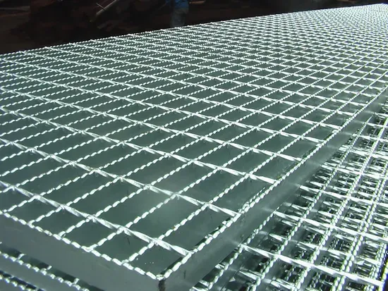
Engineer-to-engineer method
The full method on this page — no invented numbers
Certified & tested
Reports on request, MTC with every order
Quote in 24 hours
Samples in 5–7 days, production 15–25
FOB Tianjin
Shipped worldwide, EXW / CIF negotiable
The method
How to Calculate Grating Load in Five Steps
This page teaches the method a grating load calculation actually follows — engineer to engineer. You will find no invented capacity figures here: every number shown is a real range we build to, and the arithmetic for your spans and loads is run by our engineers when you send it. Work the five steps once and you will read any load table we send back with confidence.
Step 1 — Define the load type: uniform, point or wheel
Every grating load calculation starts by naming what is pushing down. A uniformly distributed load (UDL), expressed as force per unit of floor area, comes from people, pallets and snow spread over the whole panel. A concentrated point load is a single heavy footprint — a machine leg or a jack stand. A wheel load is a point load that also rolls, landing between two bearing bars at worst. The three behave differently, and one panel usually has to answer to more than one of them at a time.
Step 2 — Trace the load down to one bearing bar
Grating is not a plate: it is a set of parallel bars, and only the bars that run across the span carry the load. The share each bar carries is set by its tributary width, which is simply the spacing between bars. Under a uniform load, the load collected by one bar equals the area load multiplied by that spacing — so halving the spacing halves the load on each bar. Our panels are built with bar spacing at 30 / 40 / 60 mm centers and bearing bars from 20×3 mm to 100×8 mm, which is why spacing is the first lever in any calculation. Cross bars help a point load find neighbouring bearing bars, but they are not the spanning members.
Step 3 — Check strength with the section modulus concept
One loaded bar is now a small beam on a span, and the strength check compares bending demand against bending capacity. Capacity comes from the section modulus of the bearing bar — a property of its cross-section that grows steeply with bar depth and mildly with bar thickness. That is the whole reason heavy panels are deep rather than merely thick, and why moving from a light to a heavy section changes capacity far more than adding a few millimetres of thickness. The comparison itself is one line of arithmetic; the honest work is knowing the support condition, which is why the final verification step exists.
Step 4 — Check deflection, where span rules everything
A bar can be strong enough and still sag enough to feel unsafe underfoot. Deflection demand grows with the span raised to the fourth power and shrinks with the bar depth raised to the third, so span length — not load alone — dominates this check. How much sag is acceptable is a design choice, not ours to invent: the limit is set by the standard, specification or client brief your project answers to. Once the limit is fixed, the check asks which bar section at which spacing stays inside it over your clear span.
Step 5 — Verify with the factory before you commit
A method this short hides real judgment calls: the true clear span after supports and banding, the load combinations your code demands, the finish. Send the numbers — our engineers verify and return the calc with your quote in 24 hours, free, with the relevant load and span tables attached. You check our work with the four steps above; that is the whole point of publishing the method.
Step 1 in detail
Uniform, Point and Wheel Loads Compared
Before any steel grating design calculation is run, the load case decides which part of the panel works hardest. This is what each type does — described by behavior, because capacities belong to your verified calculation, not to a web page.
| Dimension | Uniform load (UDL) | Point load | Wheel load |
|---|---|---|---|
| What it is | Force spread over the floor area, quoted as load per unit area | One concentrated force at a small contact patch | A point load that rolls and can land anywhere on the panel |
| Typical source | People, stored goods, snow, equipment mass | Machine legs, jack stands, pipe supports | Forklifts, trolleys, vehicles on ramps and docks |
| How it reaches a bar | Area load × bar spacing = the load one bearing bar carries per unit of length | Sharpest when it sits directly over one bearing bar; cross bars share it with neighbours | Worst case placed between two bars, loading both plus local cross-bar bending |
| What it usually governs | The overall bar section for the span — the sizing case | Local bending of bars and cross bars at the contact zone | Heavier bars at closer centers, plus locked or banded edges |
| Honest note | Simplest case to check by hand with the five steps above | Position matters more than magnitude — the same load can be harmless or decisive | Assessed per project; wheel paths and turning zones change the answer |
Working a real case through all five steps? Send your spans and loads — we run the numbers and return the calc with your quote.
Steps 2 and 4, drawn
From Floor Load to One Loaded Bar
1 · Bars span, cross bars connect
Only bars running across the clear span carry load — spec the panel so bearing bars sit the short way, and note the real span after supports and banding.
2 · The tributary strip sets the share
One bar collects the load from a strip as wide as its spacing. Closer centers — 30 / 40 / 60 mm on our panels — share the same floor load across more bars.
3 · Deflection against a chosen limit
The limit line is a design decision from your standard or brief; the check confirms the bar section and spacing keep the sag inside it across the clear span.
Steps 3 and 4, conceptual
A Steel Grating Design Calculation Is Two Checks
Strip away the unit conversions and every load question reduces to the same pair of comparisons. Here is what each one is really asking, in words rather than worked numbers — the worked numbers come back with your quote.
Strength: demand versus section
Bending demand follows from the load one bar carries and the span it crosses; capacity follows from the bar's section modulus. Depth does the heavy lifting, thickness adds the margin — the reason deep bars at reasonable centers beat thin dense ones for heavy floors.
Deflection: feel and drainage
Sag scales with the fourth power of span, so a modest span increase can outrun a bigger bar. A limit stated as a fraction of the span is chosen by your project — pedestrian comfort, ponding on drainage floors and tolerance for supported services all push it tighter.
Boundary conditions: the honest variable
The same bar section answers differently on welded versus bolted supports, with banded edges, over a drain pit or on a mezzanine trimmer. That judgment — not the arithmetic — is what our engineers add in step 5, and why we verify before anything is cut.
What the method sizes
The Ranges the Calculation Lands On
| Parameter | Range |
|---|---|
| Bearing bar | 20×3 mm to 100×8 mm, plain or serrated |
| Bar spacing | 30 / 40 / 60 mm centers |
| Cross bar | Twisted square or round, per specification |
| Panel width | Up to 1.25 m |
| Panel length | Up to 6 m |
| Materials | Q235B carbon steel · SS304 / SS316 stainless |
| Surface | Black or hot-dip galvanized (ASTM A123 / ISO 1461) |
| Stock designation | 19W4 and custom equivalents |
Load tables come with your quote
We deliberately do not publish a generic load table: the right one depends on your span, spacing and load case. Send your numbers and factory engineers return the calculation with the relevant load and span charts — free, within the 24-hour quote. Materials and paperwork behind every answer:
- Mill test certificate to EN 10204 Type 3.1
- Factory inspection report with every shipment
- Declaration of Conformity prepared per order destination
When the calculation points to bigger bars and closer centers, see heavy-duty grating; when span is the constraint, start from grating maximum span length.
Standards & compliance
Load Checks Run Against Recognized Practice — Documents on Request
ANSI / NAAMM MBG 531
Panels produced to MBG 531 reference practice, with load method and weld inspection on our five-stage QC plan.
ASTM A123 / ISO 1461 HDG
Hot-dip galvanized coating thickness checked by sampling on every galvanized batch before panels are released.
CE & SGS tested
Certified & tested, reports on request — we show documents you can verify, not a certificate wall.
Step 5 — verification
Send the Numbers — We Verify, Free
Send your span, spacing and load
Clear span and bearing-bar direction, the load type with magnitude — uniform, point or wheel — and your material and finish. A sketch is enough; drawing review is free.
Engineers verify the calculation
We work the same five steps with real sections, check the boundary conditions, and attach the load and span tables that match your case.
The calc returns with your quote
Send the numbers — our engineers verify and return the calc with your quote in 24h. Request grating load charts too: free, by return email, no obligation.
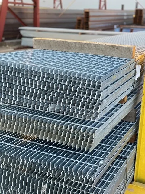
Factory-direct quote
Request a Grating Load Calculation
Free, no obligation — an engineer-checked calculation and the matching load tables land with your itemized quote within 24 hours.
- Five-stage QC, from MTC verification at goods-in to final inspection
- DoC, MTC EN 10204 3.1 and inspection report with every order
- Factory audits welcome — see the lines before you commit
Prefer to talk? WhatsApp us or sales@dtsteelladder.com
Request your calculation
Five fields — we do the rest.
FAQ
Frequently Asked Questions
How do you calculate grating load step by step?
Define the load type first — uniform, point or wheel. Trace that load to a single bearing bar: a uniform load lands on one bar as load per length times the bar spacing. Compare the bending demand against the bar section capacity, then check deflection against the limit your project sets. Finally, have factory engineers verify the numbers — we return the calculation with your quote in 24 hours.
What inputs do I need for a steel grating design calculation?
Four inputs: the clear span and the direction the bearing bars run; the bar section and spacing if known — our range runs 20×3 mm to 100×8 mm bars at 30 / 40 / 60 mm centers; the load type with magnitude, uniform, point or both; and the material with finish, Q235B or SS304 / SS316, black or hot-dip galvanized.
Do you provide grating load tables with the calculation?
Yes, free and by return email. We do not publish generic load tables, because the right table depends on your span, spacing and load case — instead the relevant load and span charts are provided with your quote. Mill certificates to EN 10204 3.1 and inspection reports travel with every order.
Related pages
Related Specification & Calculator Pages
Grating Load Calculator
The format-agnostic calculator route — inputs, checks, honest output.
View page →Bar Grating Load Calculator
The four inputs and three checks behind a bar grating load answer.
View page →Grating Deflection Calculator
Step 4 in depth — sag, span and the limits you choose.
View page →Grating Load Table
How load tables are read once the method is clear.
View page →Grating Maximum Span Length
Span direction and limits — the variable deflection loves most.
View page →Grating Load Bar
The bearing bar itself — sections, spacing and what each carries.
View page →